Products
Pump Selector
Explosion-Proof Pumps
Gas Analyzer Pumps
Services
Diaphragm Pump Repair Videos
Frequently Asked Questions
Head Connection Schematics
Gas Diaphragm Pump Spare Parts
Contact Us
How To Order
Knowledge Hub
Dia-Vac® Gas Diaphragm Pump Technology
Combination Curves
Fenceline Monitoring
Gas Sample System Design Using Diaphragm Pumps
Methods for Diaphragm Pump Selection
Standard Motors
Solution For Safe & Reliable Gas Transfer
SCR Monitoring with ADI RSeries Pumps
About Us
News
Back to the product list

M-Series Dia-Vac® Pump Double Head Hazardous Area

The M-Series Dia-Vac® is now available with a variety of hazardous area motors.

The “Mini” Dia-Vac® is the classic workhorse pump for your system.

The capacity to flow 20 LPM in a small, but rugged design has made this a staple in hazardous area CEMS systems worldwide.

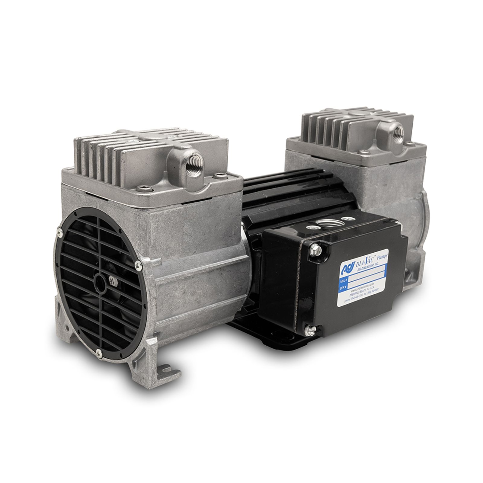
ADI’s gas sampling Dia-Vac® Pumpscan pass your gas at the speed of need! Due to an increased interest in reducing the pressure, vacuum, and/or flow on the Dia-Vac® pumps, our engineers designed a modified eccentric design.

This allows you to customize your Dia-Vac® pump to meet your application requirements while at the same time increasing the diaphragm and bearing life. The standard eccentric size is 0.160 on theM-Series Dia-Vac® Pump. Please note that the chart below is not meant to be read as a combination of pressure and vacuum at the same time, only pressure or vacuum.

M-Series Dia-Vac®

Flow Averages

(Please click on individual Model # for actual performance curves)


Model#

PSIG (Max Pressure)

Bar Gauge (Max Pressure)

InHg Gauge (Ultimate Vacuum)

Mbar Gauge (Ultimate Vacuum)

SCFM (Max Flow)

SLPM (Max Flow)


M081

6

0.41

7

237

0.42

12

M081.pdf

M081- Metric


M081_Metric.pdf

M101

17

1.17

17

575

0.49

14

M101.pdf

M101- Metric


M101_Metric.pdf

M121

19

1.31

18

609

0.59

16.8

M121.pdf

M121- Metric


M121_Metric.pdf

M151

29.1

2

19.7

667

0.7

20

M151.pdf

M151- Metric


M151_Metric.pdf

M161

35

2.41

20.7

701

0.75

21.4

M161.pdf

M161- Metric


M161_Metric.pdf

M162 (Para)

35

2.41

21

711

1.3

39

M162-Parallel-Combo-Curve.pdf

M162- Metric


M162_Metric.pdf

Head Connection Schematics

CAPACITY

WETTED MATERIALS

MOTOR

OPTIONS

STYLE

ECC.

HEADS

HEAD

DIAPHRAGM

TYPE

VOLTS

Hz

OPTIONS

M=M-Series

16

1

A=Alum

E=Encap Tef/EPDM*

C=Gen. Purpose

A=115 AC

0= N/A

• L=Elevated Head

15

2

B=Tef/Alum

N=EPDM

W=XP Div.2

B=230 AC

1=60 1Ph

• M=Heated w/K Thermocouple

14

F=316ss

P=All Teflon

Z=ATEX Zone 2 IIC

X=N/A

2=50 1 Ph

• M1=Heated w/RTD M2=Heated 65° T-stat

12

G=316ss (TefCo)

T=Tef/EPDM

• M3=Heated 100° T-stat

10

H=Hastelloy C

• M4=Heated 140° T-stat

8

J=Hast. C (TefCo)

• M5=Heated 163° T-stat

L=Silconert®316ss

• M6=Heated 200° T-stat

T=Solid Teflon

P=Electro Polish

*Teflon Head Only